As the core equipment that converts mechanical energy into electrical energy, the generator runs through all aspects of power production, industrial operation, and daily life. From megawatt level units in large power plants to small portable power generation equipment, its core working logic always revolves around Faraday's law of electromagnetic induction, combined with precise mechanical structure and electromagnetic design, to achieve stable and efficient electrical energy output. The following will comprehensively disassemble the working mechanism of the generator from the aspects of core principles, basic structure, workflow, illustrated diagrams, and type differences, making the complex principles intuitive and easy to understand.
The core working principle of a generator originates from Faraday's discovery of electromagnetic induction in 1831. This law clearly states that when a conductor coil cuts magnetic induction lines in a magnetic field or when the magnetic flux passing through the coil changes over time, induced electromotive force will naturally be generated at both ends of the coil; If the coil is connected to a closed circuit, the induced electromotive force will drive the directional movement of charges, forming an induced current. The core formula of this process can be expressed as $$\ varepsilon=- N \ frac {d \ Hi-B} {dt} $$, where $$\ varepsilon $$represents induced electromotive force, $$N $$is the number of coil turns, and $$\ Hi-B $is the magnetic flux passing through the coil. The formula clearly indicates that the magnitude of induced electromotive force is proportional to the number of coil turns and the rate of change of magnetic flux, which is also the core basis for optimizing power generation efficiency in generator design.
To achieve continuous electromagnetic induction and stable output of electrical energy, the generator needs to have a precise collaborative structure, where each component plays its own role and cooperates with each other to form a complete energy conversion system. Its main components include stator, rotor, excitation system, prime mover, as well as slip rings, brushes or commutators used for current extraction. Among them, the stator is a fixed core component composed of a stator core and a three-phase armature winding. The stator core is made of stacked silicon steel sheets, which can effectively reduce eddy current losses. The armature winding is the key carrier of induced and output electrical energy; The rotor is a rotatable component, usually composed of excitation windings or permanent magnets. When direct current is applied, it forms an electromagnet with alternating N and S poles, providing a stable magnetic field for power generation; The function of the excitation system is to deliver stable DC excitation current to the rotor winding, ensuring constant magnetic field strength and guaranteeing the stability of the generated voltage; The prime mover is the "power source" of the generator, whether it is the steam turbine of a thermal power station, the water turbine of a hydropower station, or the diesel engine or gasoline engine of a small generator, its core function is to provide continuous rotating mechanical energy to drive the rotor to rotate at high speed; Slip rings and brushes (mostly used in AC generators), as well as commutators (mostly used in DC generators), are responsible for extracting the electrical energy generated by the coils, ensuring the continuity and directionality of the current output.
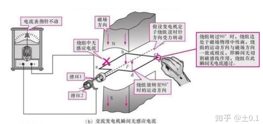
Among various types of generators, AC synchronous generators are the most widely used. Whether it is large thermal, hydraulic, nuclear power plants, or the main power supply equipment in industrial production, this type of generator is basically adopted. Its complete working process can be divided into five coherent steps, which can be more intuitively understood by combining diagrams: the first step is excitation field construction, where the excitation system applies DC power to the rotor winding to convert the rotor into a strong electromagnet, forming a stable alternating magnetic pole (N pole and S pole alternating arrangement), which is the basis of power generation; The second step is mechanical drive, where the prime mover is started by a primary energy source (coal, water, wind, nuclear energy, etc.), which drives the rotor to rotate at a constant speed at high speed, and then drives the alternating magnetic poles on the rotor to rotate synchronously, forming a rotating magnetic field; The third step is the change of magnetic flux. The high-speed rotating magnetic field continuously cuts the armature winding on the stator. Due to the alternation of rotor magnetic poles, the magnetic flux passing through the stator coil will show periodic changes over time, sometimes increasing and sometimes decreasing, and the direction will continue to alternate; The fourth step is induction power generation. According to Faraday's law of electromagnetic induction, the periodic variation of magnetic flux in the stator coil will excite the generation of sinusoidal alternating electromotive force. The three-phase armature windings on the stator are spaced 120 ° apart from each other, resulting in three sets of alternating electromotive forces with phase differences of 120 °, which together form three-phase alternating current; The fifth step is current output, which is transmitted to the power grid or directly supplied to various loads through the output terminals of the stator winding to complete the output of electrical energy. The output frequency can be calculated using the formula $f=\ frac {Pn} {120} $, where $f $$is the output frequency (in Hz), $$P $$is the number of rotor magnetic poles, and $n $is the rotor speed (in rpm). This is also the key principle for maintaining a constant power grid frequency.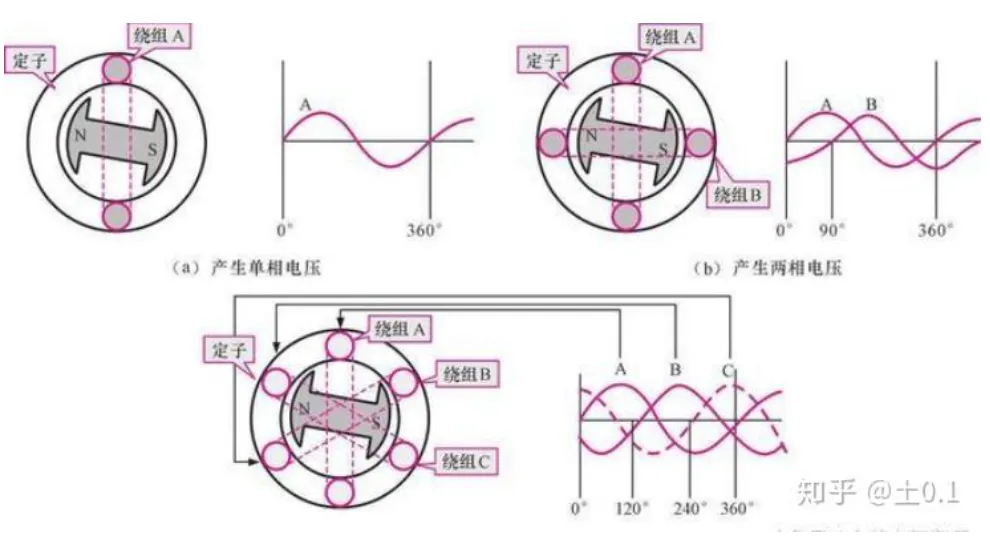
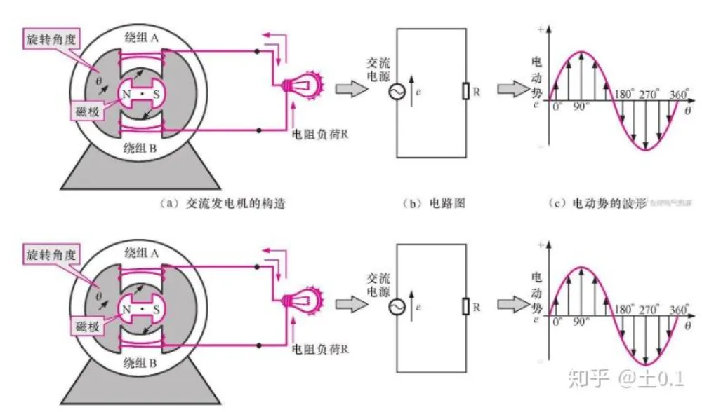
Combining diagrams can provide a clearer understanding of the working logic of a generator. Common diagrams can be divided into three categories: one is the schematic diagram of the principle of a single-phase AC generator. Usually, the left side shows the position of the coil at different rotation angles in the magnetic field, visually presenting the process of cutting magnetic induction lines by the coil. The middle is marked with rectification and output structure. The right side is the output sine AC waveform, which can clearly see that the current direction will reverse once every half rotation of the coil, which is also the core feature of AC power; The second is the winding and output waveform diagram of a three-phase AC generator, which respectively indicates the arrangement of single-phase, two-phase, and three-phase windings, focusing on the structural characteristics of the three-phase windings with a spatial difference of 120 °. At the same time, three sets of AC voltage waveforms are presented, which can intuitively understand the reasons for the formation of phase difference in three-phase electricity. Due to stable power supply and high efficiency, three-phase electricity has become the mainstream form of industrial power supply and grid transmission; The third is the synchronous generator structure and excitation process diagram, which clearly indicates the positions and connection relationships of various components such as stator, rotor, excitation system, slip ring, and electric brush. It gradually demonstrates the complete process of excitation current entering the rotor, rotor generating magnetic field, prime mover driving rotor rotation, magnetic field cutting stator winding, and electrical energy output, making abstract working principles concrete and facilitating quick understanding of the collaborative effects of various components.
In addition to the most widely used AC generator, DC generator also has certain applications in small low-voltage scenarios. The core difference between the two lies in the current extraction method and structural design: AC generator uses a combination of slip ring and brush to extract current, the slip ring rotates synchronously with the rotor, and the brush is fixed and stationary. The AC generated by the coil is extracted through the contact between the two, and its structure is relatively simple, with low wear and maintenance costs, suitable for high-power power generation scenarios; The DC generator, on the other hand, is equipped with a commutator at the end of the rotor coil. The commutator is composed of multiple split copper rings, which rotate with the rotor and convert the alternating current in the coil into a constant direction of direct current through contact with fixed brushes before being drawn out. However, its structure is relatively complex, and the wear of the commutator and brushes is high, resulting in high maintenance costs. Therefore, it is mostly used in small low-voltage DC power sources, such as small portable DC generators and old-fashioned car generators.
While understanding the working principle of the generator, it is also necessary to master several key supplementary points to further improve cognition: from the perspective of energy conversion path, the entire working process of the generator is essentially the transfer and conversion of energy, that is, primary energy (coal, water, wind, nuclear energy, etc.) is converted into mechanical energy through the prime mover. The prime mover transfers the mechanical energy to the rotor, and the rotor rotates to generate a rotating magnetic field. The magnetic field cuts the stator winding and converts it into electrical energy through electromagnetic induction, ultimately outputting it for various loads to use. The entire process is energy conservation, without additional energy generation, only realizing the conversion of energy forms; From the perspective of physical laws, the working process of a generator also follows Lenz's law, which states that the magnetic field generated by induced current will hinder the change of the original magnetic field. Therefore, during the power generation process, the rotor will be subjected to electromagnetic resistance, which requires the prime mover to continuously input mechanical energy, overcome electromagnetic resistance, maintain a constant speed of the rotor, and ensure the stability of electrical energy output; From an industrial application perspective, large power plants commonly use rotating magnetic field synchronous generators, which have a fixed stator and rotating rotor excitation structure. Compared to rotating coil generators with a rotor as a coil and a stator as a magnetic field, this structure can effectively reduce safety hazards and energy losses caused by high-voltage and high current rotating contacts, improve power generation efficiency and stability, and is also the core design concept of large generators.
In summary, the working principle of the generator is based on Faraday's law of electromagnetic induction. Through the collaborative action of components such as the stator, rotor, excitation system, and prime mover, stable conversion of mechanical energy to electrical energy is achieved. Among them, AC synchronous generators have become the mainstream application type due to their simple structure, high efficiency, and stable power supply, while DC generators are suitable for small low-voltage scenarios. Combining diagrams can provide a more intuitive understanding of its working logic, the roles of various components, and the energy conversion process. Whether it is the operation of large power plants or the use of small portable generators, the core principles remain consistent, with only differences in structural complexity and power scale.